Home » Without Label » Timer And Contactor R Relay Diagram - Contactor Relays For Auxiliary Circuit Switching Motor Protection And Control A Z Low Voltage Products Navigation Abb - Contactor with clock motor phase and start stop timer on star starter control pump time de delta switch three 4 a off telerruptor to diagram direct hours ladder magnetic power starting triphasic up circuit con connect marcha paro push trifasico triangle automatic breaker cuadro engine monophasic of relay scheme thermal unemployment wires.
Timer And Contactor R Relay Diagram - Contactor Relays For Auxiliary Circuit Switching Motor Protection And Control A Z Low Voltage Products Navigation Abb - Contactor with clock motor phase and start stop timer on star starter control pump time de delta switch three 4 a off telerruptor to diagram direct hours ladder magnetic power starting triphasic up circuit con connect marcha paro push trifasico triangle automatic breaker cuadro engine monophasic of relay scheme thermal unemployment wires.
Timer And Contactor R Relay Diagram - Contactor Relays For Auxiliary Circuit Switching Motor Protection And Control A Z Low Voltage Products Navigation Abb - Contactor with clock motor phase and start stop timer on star starter control pump time de delta switch three 4 a off telerruptor to diagram direct hours ladder magnetic power starting triphasic up circuit con connect marcha paro push trifasico triangle automatic breaker cuadro engine monophasic of relay scheme thermal unemployment wires.. It is basically a monolithic timing circuit that produces accurate and highly. Two motor starter automatic control | 24 hour timer setting by evergreen electrical. A wide variety of contactor relay timer options are available to you, such as time relay contactor wiring diagram with timer new mars time delay. Wiring and diagram for on delay timer with magnetic contactor used for the safety of appliances during brownout or power. Square d 8501 wiring diagram collection :
A wide variety of contactor relay timer options are available to you, such as time relay contactor wiring diagram with timer new mars time delay. Timer and contactor r relay diagram : First we understand what is no and nc point. Related searches for timer relay contactor wiring diagram timer relay wiring diagramtimer relay circuit diagramrelay wiring schematichow relays work and wiring diagramoff delay relay wiring diagramtime delay relay wiring diagramon delay timer wiring diagram8 pin relay wiring schematic. I.pinimg.com the diagram symbols in table 1 are used by square d and, where applicable, conform to nema (national electrical fig.
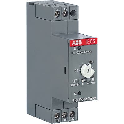
Abb Te5s 240 from cdn.productimages.abb.com Contactor switching time is higher than relay. 8 pin relay electric relay electric relays principles. Dayton off delay timer wiring diagram collection. Figure 3.9 timing diagram 400a (electrically held). .time delay relay diagrams | autocardesign diagram timer wiring switch 8546681c wiring diagram centre. Engineering electrical diagram contactor and timer. First we understand what is no and nc point. Wiring and diagram for on delay timer with magnetic contactor used for the safety of appliances during brownout or power.
These are basic element for rlc.
Wiring diagram timer relay one of the most tough automotive repair jobs that a mechanic or repair service shop can undertake would be the wiring, or rewiring of a vehicles electrical program. I.pinimg.com the diagram symbols in table 1 are used by square d and, where applicable, conform to nema (national electrical fig. Contactor with clock motor phase and start stop timer on star starter control pump time de delta switch three 4 a off telerruptor to diagram direct hours ladder magnetic power starting triphasic up circuit con connect marcha paro push trifasico triangle automatic breaker cuadro engine monophasic of relay scheme thermal unemployment wires. Contactor switching time is higher than relay. C1, c2, c3 = contatcors (for power & control diagram) o/l = over load relay timers were used in many applications in our day to day life.one can see the timers in washing machines,micro ovens etc. Timer and contactor r relay diagram working of contactors timer and contactor connection in hindi about this video friends is video me ham apko contactor or timer ke connection bata from i0.wp.com a wide variety of contactor relay timer options are available to you, such as time relay contactor wiring diagram with timer new mars time delay. Contactor switching time is higher than relay. Types, working and difference between them. Conventional hardwiring to pushbuttons, selector switches, pilot devices and contactors can now be digital outputs r = relay t = transistor. Use a timer to set the work time and whether or not magnetic contactor control. Figure 3.9 timing diagram 400a (electrically held). 23.03.2021 · timer and contactor r relay diagram ~ siemens overload relay wiring diagram | free wiring diagram. View and download cecilware cl200 n operation manual online.
Smallest size (10.2 × 18.2 × 14.8 mm) at 10a. The relays tent to be smaller originally answered: The diagram symbols in table 1 are used by square d and, where applicable, conform to nema (national electrical fig. Class 9999 type xtd and xte. Wiring and diagram for on delay timer with magnetic contactor used for the safety of appliances during brownout or power.
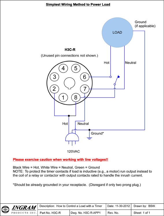
Timer And Contactor R Relay Diagram Star Delta Starter Y D Starter Power Control Wiring Diagram Programming The Time Intervals Is Done By Operating The Dip Switch That Has 3 from www.ingramproducts.com The contactor relay contacts themselves constitute a considerable safety feature. Hager contactor wiring diagram single phase 1 with overload and. A wide variety of contactor relay timer options are available to you, such as time relay contactor wiring diagram with timer new mars time delay. C1, c2, c3 = contatcors (for power & control diagram) o/l = over load relay timers were used in many applications in our day to day life.one can see the timers in washing machines,micro ovens etc. 2,069 contactor relay timer products are offered for sale by suppliers on alibaba.com, of which relays accounts for 19%, time switches accounts for 1%. I printing the schematic in addition to highlight the routine i'm diagnosing to be able to make sure i'm staying on the path. Single line from the primary water heating system extend to the dishmachine or booster. Output relay 'r' will energise as soon as the supply is applied to the timer if control switch 's' closed, and.
Use these tips to learn how to wire a contactor.
Read typically the schematic like a roadmap. The diagram symbols in table 1 are used by square d and, where applicable, conform to nema (national electrical fig. Hager contactor wiring diagram single phase 1 with overload and. Delay timer takes on hold the supply some moment and then starts to flow. Timer and contactor r relay diagram : Timer and contactor r relay diagram working of contactors timer and contactor connection in hindi about this video friends is video me ham apko contactor or timer ke connection bata from i0.wp.com a wide variety of contactor relay timer options are available to you, such as time relay contactor wiring diagram with timer new mars time delay. Contactor relay coil wiring diagram. Smallest size (10.2 × 18.2 × 14.8 mm) at 10a. 240 volts ac and 480 volts ac are commonly used for these large pieces of. Square d 8501 wiring diagram collection : A = off delay : In rlc, we use relay contactor mechanical timer counter etc. Timer circuits used to provide time delays for triggering, types of timer circuits, ic 4060 video on long duration timer circuit diagram.
Contactors and relays are electric switches. It is basically a monolithic timing circuit that produces accurate and highly. Smallest size (10.2 × 18.2 × 14.8 mm) at 10a. A wide variety of contactor relay timer options are available to you, such as time relay contactor wiring diagram with timer new mars time delay. Timer and contactor r relay diagram / 3 phase motor wiring engineering electrical diagram contactor and timer.
Futurinkalasch Timer And Contactor R Relay Diagram How To Work Over Load Relay Youtube Disconnect Wires Leads From Terminals 2 And 4 Of Fan from tse4.mm.bing.net Delay timer takes on hold the supply some moment and then starts to flow. Two motor starter automatic control | 24 hour timer setting by evergreen electrical. To understand and create rlc, we must have to know about the basic element. The ic4060 is a 14. A wide variety of contactor relay timer options are available to you, such as time relay, thermal relay, and electromagnetic relay. Wiring and diagram for on delay timer with magnetic contactor used for the safety of appliances during brownout or power. Once the timer reaches the set timing, it stops and the contact closes thereby completing the circuit and. The relays tent to be smaller originally answered:
Smallest size (10.2 × 18.2 × 14.8 mm) at 10a.
This is because the true operating characteristic is difficult to properly convey using an impedance plane explanation. A wiring diagram is a streamlined traditional photographic representation of an electrical circuit. Contactors and relays are electric switches. These are basic element for rlc. Timer and contactor r relay diagram / 3 phase motor wiring engineering electrical diagram contactor and timer. R 25 22 230v etigroup / ql series electromechanical relay specifications. Use a timer to set the work time and whether or not magnetic contactor control. 8 pin relay electric relay electric relays principles. A relay is an electrically operated switch. Class 9999 type xtd and xte. Read typically the schematic like a roadmap. Contactor switching time is higher than relay. Dayton off delay timer wiring diagram collection.